Fluid system elements
Detailed distributed models of fluids, such as the Navier-Stokes equations, are necessary for understanding many aspects of fluid systems and for guiding their design (e.g. a pump or an underwater vehicle). However, a great many fluid systems are networks of pipes, tanks, pumps, valves, orifices, and elevation changes—and at this system-level, a different approach is required.
As with electrical and mechanical systems, we can describe fluid systems as consisting of discrete lumped-parameter elements. The dynamic models that can be developed from considering these elements are often precisely the right granularity for system-level design.
We now introduce a few lumped-parameter elements for modeling fluid systems. Let a volumetric flowrate \(Q\) and pressure drop \(P\) be input to a port in a fluid element. Since, for fluid systems, the power into the element is \[\begin{aligned} \mathcal{P}(t) &= Q(t) P(t) \end{aligned}\] we call \(Q\) and \(P\) the power-flow variables for fluid systems. A fluid element has two distinct locations between which its pressure drop is defined. We call a reference pressure ground.
Work done on the system over the time interval \([0,T]\) is defined as \[\begin{aligned} W \equiv \int_0^T \mathcal{P}(\tau) d\tau. \end{aligned}\] Therefore, the work done on a fluid system is \[\begin{aligned} W = \int_0^T Q(\tau) P(\tau) d\tau. \end{aligned}\]
The pressure momentum \(\Gamma\) is \[\begin{aligned} \Gamma(t) = \int_0^t P(\tau) d\tau + \Gamma(0). \end{aligned}\] Similarly, the volume is \[\begin{aligned} V(t) = \int_0^t Q(\tau) d\tau + V(0). \end{aligned}\]
We now consider two elements that can store energy, called energy storage elements; an element that can dissipate energy to a system’s environment, called an energy dissipative element; and two elements that can supply power from outside a system, called source elements.
Fluid inertances
When fluid flows through a pipe, it has a momentum associated with it. The more mass (fluid density by its volume) moving in one direction and the faster it moves, the more momentum. This is stored kinetic energy. The discrete element we now introduce models this aspect of fluid systems.
A fluid inertance is defined as an element for which the pressure momentum \(\Gamma\) across it is a monotonic function of the volumetric flowrate \(Q\) through it. A linear inertance is such that \[\begin{aligned} \label{eq:inertance_linear} \Gamma(t) = I Q(t), \end{aligned}\] where \(I\) is called the inertance and is typically a function of pipe geometry and fluid properties. This is called the element’s constitutive equation because it constitutes what it means to be an inertance.
Although there are nonlinear inertances, we can often use a linear model for analysis in some operating regime. The elemental equation for a linear inertance can be found by time-differentiating to obtain \[\begin{aligned} \frac{d Q} {d t} = \frac{1} {I} P. \end{aligned}\] We call this the elemental equation because it relates the element’s power-flow variables \(Q\) and \(P\).
An inertance stores energy as kinetic energy, making it an energy storage element. The amount of energy it stores depends on the volumetric flowrate it contains. For a linear inertance, \[\begin{aligned} \mathcal{E}(t) = \frac{1} {2} I Q(t)^2. \end{aligned}\]

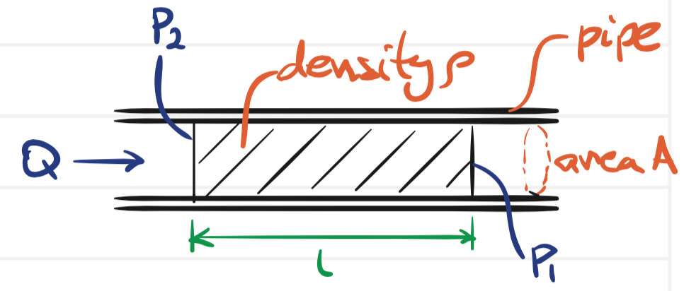
The inertance \(I\) for a uniform pipe can be derived, as follows, with reference to the sectioned pipe of figure 8.1. For an incompressible fluid flowing through a pipe of uniform area \(A\) and length \(L\), with uniform velocity profile (a convenient fiction), an element of fluid obey’s Newton’s second law, from which several interesting equalities can be derived: \[\begin{aligned} F &= m \frac{d v} {d t} \Rightarrow \\ \frac{F} {A} &= \frac{m} {A} \frac{d v} {d t} \Rightarrow \\ P &= \frac{\rho A L} {A} \frac{d v} {d t} \\ &= \rho L \frac{d} {d t} \left(\frac{Q} {A}\right) \\ &= \frac{\rho L} {A} \frac{d Q} {d t} \Rightarrow \\ \frac{d Q} {d t} &= \underbrace{\frac{A} {\rho L}}_{1/I} P. \end{aligned}\]
From this last equality, it is clear that, for a uniform pipe and the assumptions, above, \[\begin{aligned} I &= \frac{\rho L} {A}. \end{aligned}\] Clearly, long, thin pipes will have more inertance. In fact, we often ignore inertance in modeling a pipe, unless it is relatively long and thin.
Fluid capacitors
When fluid is stored in tanks or in pressure vessels, it stores potential energy via its pressure drop \(P\). For instance, a tank with a column of fluid will have a pressure drop associated with the height of the column. This is analogous to how an electronic capacitor stores its energy via its voltage. For this reason, we call such fluid elements fluid capacitors.
A linear fluid capacitor with capacitance \(C\), pressure drop \(P\), and volume \(V\) has the constitutive equation \[\begin{aligned} V = C P. \end{aligned}\] Once again, time-differentiating the constitutive equation gives us the elemental equation: \[\begin{aligned} \frac{d P} {d t} = \frac{1} {C} Q, \end{aligned}\]
Fluid capacitors can store energy (making them energy storage elements) in fluid potential energy, which, for a linear capacitor is \[\begin{aligned} \mathcal{E}(t) = \frac{1} {2} C P^2. \end{aligned}\]
Fluid resistors
Fluid resistors are defined as elements for which the volumetric flowrate \(Q\) through the element is a monotonic function of the pressure drop \(P\) across it. Linear fluid resistors have constitutive equation (and, it turns out, elemental equation) \[\begin{aligned} Q = \frac{1} {R} P \end{aligned}\] where \(R\) is called the fluid resistance.
Fluid resistors dissipate energy from the system (to heat), making them energy dissipative elements.
Flowrate and pressure drop sources
Fluid sources include pumps, runoff, etc.
An ideal volumetric flowrate source is an element that provides arbitrary energy to a system via an independent (of the system) volumetric flowrate. The corresponding pressure drop across the element depends on the system.
An ideal pressure drop source is an element that provides arbitrary energy to a system via an independent (of the system) pressure drop. The corresponding volumetric flowrate through the element depends on the system.
Real sources, usually pumps, cannot be ideal sources, but in some instances can approximate them. More typical is to include a fluid resistor in tandem with an ideal source, as we did with electrical resistors for real electrical sources.
Generalized element and variable types
In keeping with the definitions of , pressure \(P\) is an across-variable and flowrate \(Q\) is a through-variable.
Consequently, the fluid capacitor is considered an A-type energy storage element. Similarly, the fluid inertance is a T-type energy storage element. Clearly, a fluid resistor is a D-type energy dissipative element.
Pressure sources are, then, across-variable sources and volumetric flowrate sources are through-variable sources.
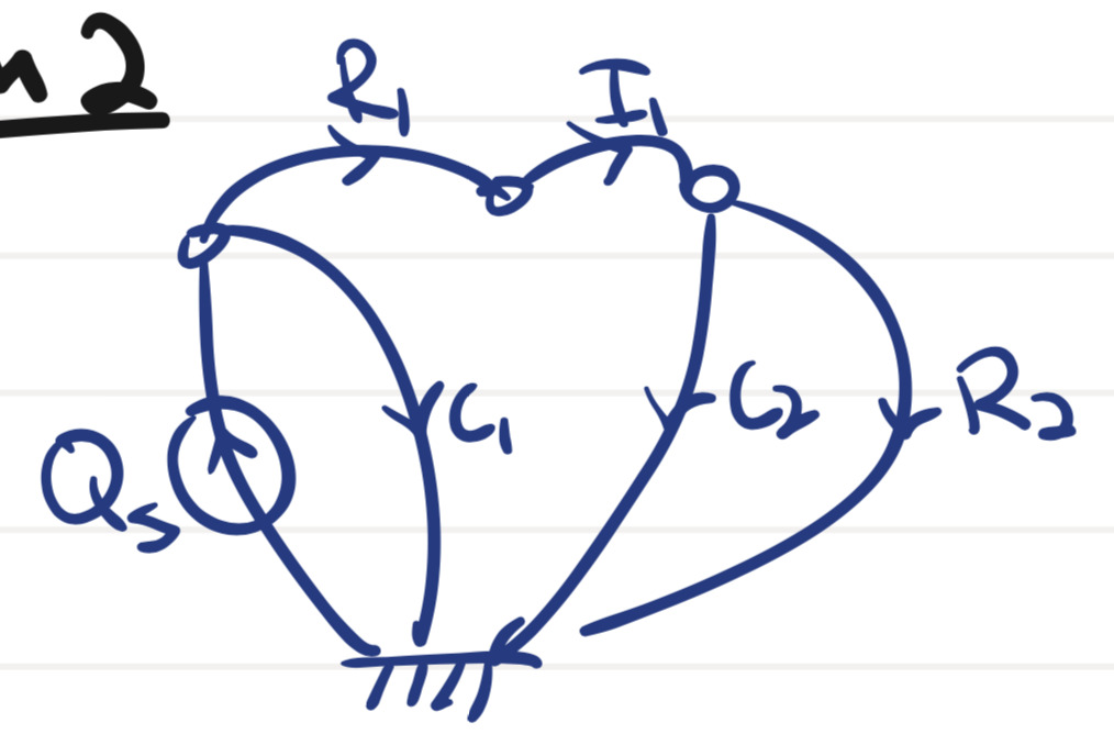
Use the schematic in figure 8.2 to draw a linear graph of the system.

Online Resources for Section 8.1
No online resources.